PinkyPi prebuilt image version 1.0 for the 1.3inch 240x240 LCD is complete and now available for download!
[download id="1176"]
Notes -
To rebuild the display driver and disable screen sleep / backlight turning off on idle use the following command over SSH.
cd ~/fbcp-ili9341/build
rm CMakeCache.txt
cmake -DWAVESHARE_ST7789VW_HAT=ON -DSPI_BUS_CLOCK_DIVISOR=6 -DSTATISTICS=0 -DBACKLIGHT_CONTROL=OFF ..
make -j
Reboot, and it will load the new version of the display driver with the backlight control turned OFF
I decided to make few mods to the screen :
i replaced the trhree button for a smoother clic and to space them a bit more .
then , i had 2 more buttons to play with neogeo games
i conneted them to 12 and 23 gpio pins ( only gpio 12 have to be uncommented in the pikypie image)
i just need to design a new case now ?
The case design is half the fun lol. I think I went through maybe 50 revisions of small changes and updates before I got the design where it is now. The pro version not so many updates as I was able to copy several of the ideas over.
Have you used Sketchup before?
i dont use sketchup , but i know SolidWorks , i tried to import you files in STL with no good resulsts . i gonna make on from zero
here my very first try for the pro version
you can chek my Thingiverse Designs from Here
Nice, I'm diggin it! Can Solid Works import the skp files that came from Sketchup or no? I do include those with each build I make
It is possible but results are bad and almost impossible to edit
It is possible but results are bad and almost impossible to edit
I've had the same issues when importing STL files into Sketchup, makes them somewhat un-usable.
Let me know if there is a format I can export them to, if it would help.
If you are just looking for the extra buttons, the Pro version may be the right way to go from the start, the screens can be had for $10 when they are on sale and the case / code is already complete.
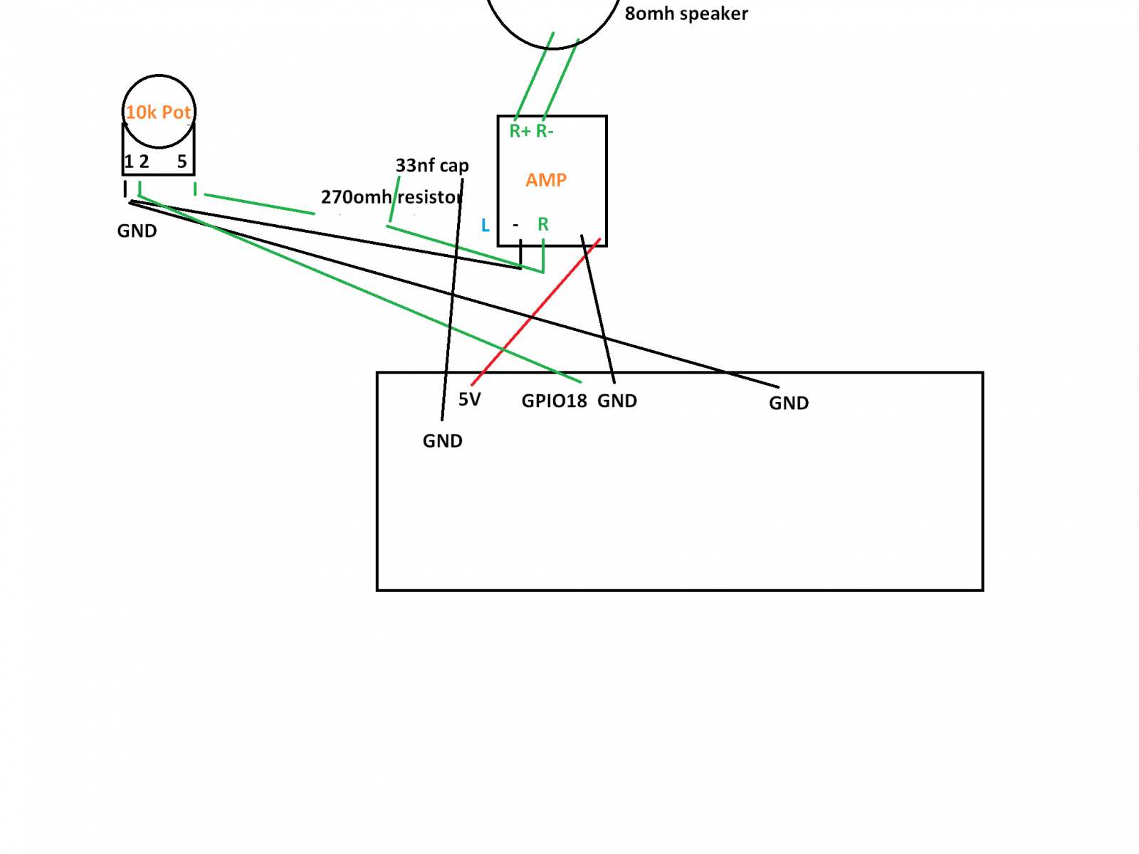
it seem you short circuit the gpio 18 to ground when volume is down . Do you really connect like that ? i think 2 and 5 are inverted
I think you very well be right, I had pulled that from a forum post I made 6 months ago while working on the audio circuit and took it as gold.
I came across this last night before bed
And shows the wiring as you mentioned, I'm going to change my setup and verify all works and update the how to. Thank you!
Nice ! it's how i connect mine and it works fine ?
Hey ! i just finsh mine , i have design another case without screws on the front panel and two extra buttons for Start and Select command
i made the files with solidworks , ask me the .Stl if you need ?
Hey ! i just finsh mine , i have design another case without screws on the front panel and two extra buttons for Start and Select command
i made the files with solidworks , ask me the .Stl if you need ?
Great work! That looks amazing!
I'd be curious to check out the STL just to see your design ideas and changes. I wont distribute utilize it in any other fashion outside of curiosity.
I had been toying with the idea of a snap together solution, but as small as I made it and thin as the walls are (1.5mm), with barely any room between the walls and the device itself, I sadly stuck with screws.
I did find an older image of my wiring when I was debating adding a headphone jack and I did have the wiring correct in that diagram, I need to update the official one, things have been hectic at my house as I am evicting someone (hence the little movement the past couple of weeks).
On a side note, I will be doing an official giveaway for a PinkyPi device, I will be posting the official details this Friday April 26th


